Fun and pain with a teardown—analogic radios are defunct
I happen to hold a master’s degree in electronics engineering. Even back in 1994 when I graduated, the world was already into digital, but I still hold dear analog electronics. It was analog electronics that drew me towards electronics; computers and software were more like a hobby. It’s therefore with justified nostalgia that I watch Big Clive’s teardowns on YouTube. His channel features more than 2,700 videos that are, most of them, teardowns of electronic equipment, with reverse engineering of the schematics and explanations of how the respective devices work.
One
This time, I ran over 📽️ a teardown by a Korean! I obviously didn’t understand a word, but I had so much fun! In the end, what I wanted to know was to find out more about the construction and the ICs used in the Philips TAR2509 radio receiver, because I couldn’t find a schematic diagram.
Gen Z can’t possibly know, but in the 70s and 80s (and in the previous decades as well), when you purchased a TV, a radio receiver, a cassette player, or a tape recorder, the schematic diagram was included with the operating instruction manual. Not anymore since the 90s. We’re living in a world where the consumer is supposed to be too lazy to care and too stupid to understand. After all, it was in the 90s that those made-up “PMPO” powers in hundreds of watts replaced the honest RMS watts. Things have changed, but the buyer doesn’t have the right to know what’s in a purchased device.
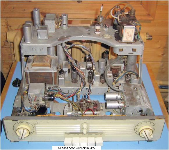
Schematic or no schematic, I had lots of fun in my teens fixing TVs, radio receivers, and cassette players. With neighbors’, some reverse engineering was often required. As for my dad’s, we started with a Soviet Рубин 102, with vacuum tubes (Radiomuseum, Reddit). It was a fascinating animal, and it even included an FM radio! Something like this.
Better TVs followed, but with questionable reliabilities: a hybrid one (back then, “hybrid” meant with both transistors and vacuum tubes), then only “solid-state” TVs, both B&W and color.
I had other “antiquities” to play with, such as a tape recorder, the Tonbandgerät Grundig TK 145 deluxe. And a vacuum tubes radio that was used, behind the Iron Curtain, to listen to Radio Free Europe, the VOA, the BBC, Deutsche Welle, Radio France Internationale, and more. I later had many semiconductor-based radio receivers, but my first love was the old one with valves. I have to admit that I wasn’t that skilled with tubes, and it was less practical and even dangerous due to the high voltages. In my teens, I was a living catalogue of semiconductor equivalences, though.
My passion for radios was due to the fact that, back then, the shortwave radio stations were, for me, some sort of Internet. I even listened on SW to Radio Swiss International, Radio Canada International, Radio Beijing, Radio Tirana, just about anything, as long as the broadcast was in Romanian, English, or French. In Ceaușescu’s last and worst decade, free information was scarce. Since 1986 I could find French press at the Bibliothèque Française (the then name of the Institut Français de Bucarest). Otherwise, we tried to receive the Bulgarian TV in the South, and people in the Western parts of Romania had better choices with the Yugoslav and Hungarian TV channels. Gen Z never heard of Yagi antennas, and even less of antenna amplifiers.
Two
Back to the teardown. My curiosity (which, so far, hasn’t managed to kill me) was drawn by a radio receiver that looked both elegant (not “fake retro”) and classic. Analog scale, rotary buttons, nothing digital, no presets, nada. Philips TAR2509 (presentation; user manual):


It doesn’t matter if the code is TAR2509/10, TAR2509/61, or TAR2509/89. There are some tiny differences depending on the market or on internal revisions.
I’ll talk about its drawbacks later. For now, what did I learn from the teardown?


I learned that Philips TAR2509 uses:
- The audio amplifier D2822N.
- The radio IC KT0936M (B9).
- Manual analog frequency adjustment via a variable resistor (a potentiometer), not a variable capacitor.
The radio IC is made by KTMicro, marketed as Quantum Microelectronics, but legally Beijing KT Micro, Ltd. So it’s not a Western nor a Japanese IC made in China; it’s an original Chinese design. The radio receiver is manufactured by MMD Hong Kong Holding Limited, one of the many Chinese companies authorized to use the “Philips” branding.
For KT0936M, there are some essential features on the official site, then some PDFs here, here, or here (also as HTML).
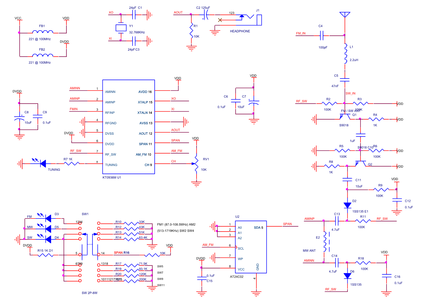
The typical application circuit from the catalog page isn’t very helpful, so I’ll try to describe the basic functioning principles below.
KT0936M (and its siblings, including KT0932M) is best described as a DSP-type (digitally-assisted) radio-on-a-chip. It includes an almost entirely digital receiver chain: a low-noise analog RF amplifier (LNA) with AGC (automatic gain control), a mixer to an IF, an ADC (analog-to-digital converter), digital filters, a DSP demodulator, and a DAC with a Class-AB audio driver. Unlike in a normal superheterodyne receiver, the AM detection/FM demodulation is replaced by DSP arithmetic!
It supports analog mechanical tuning via a variable resistor (a 10 kΩ potentiometer). It only requires an external 32.768 kHz crystal, and it can optionally use an EEPROM (24LC02) to read configuration such as which SW bands to use (KT0932M lacks SW support). The built-in MCU (microcontroller unit) controls the entire logic, including the translation of the DC voltage from the 10 kΩ tuning potentiometer into frequency. The external RF amp with 2 transistors is optional and only used for SW and FM.
The specs are rather good IMO, especially the sensitivity (given, as always, at an SNR of 26 dB for FM and 20 dB for AM): 1.6 μV in FM and 16 μV in AM (MW). The audio amp (mono!) has an SNR (FM/AM) of 58dB/55dB and a THD of 0.3%.
In FM, the selectivity at ±200 kHz is 40–51 dB, and the mirror image is cut by 43 dB. In AM, I can’t see any selectivity given (the AM spacing is 9 kHz in LW/MW except for the Americas, where it’s 10 kHz, and 5 kHz in SW, but this chip allows 1 kHz spacing.)
This guy works at 3 V (2.1-3.6 V), and it takes 27-28 mA.
As far as the AF amplifier is concerned, the D2822N from Shaoxing Silicore Technology is a clone of the TDA2822 originally introduced in the mid-1980s by SGS (now STMicroelectronics). It is a dual-channel amplifier, so it can drive stereo headphones or, in bridge mode, a single mono loudspeaker.
In bridge mode, the maximum output power depends on the working voltage (1.8 to 15 V), which in this receiver is 3 V. The catalog says, typ. 350 mW (min. 200 mW) on RL = 4 Ω at Vcc = 3 V. So how can Philips claim 300 mW when the speaker has 8 Ω? And that’s for 10% THD! 0.2% THD can be obtained for 0.5 W on 8 Ω, but at Vcc = 6 V, which can typically drive 1.35 W at 10% THD.
The low power output is, to me, the biggest disappointment in this radio receiver!
Some official data: 21×13.5×6 cm, 100 mm speaker, 300 mW, powered by 2×(L)R20 (aka D) batteries or AC. I’m not so sure about those 300 mW!
UPDATE: In bridge mode (mono), D2822N’s datasheet only mentions at Vcc = 3 V the output power on 4 Ω (typ. 350 mW, min. 200 mW), but TDA2822N’s datasheet also mentions the output power on 8 Ω: typ. 220 mW. So there is no way this radio could get 300 mW on 8 Ω at 3 V.
Three
I then explored an older relative of this radio, with rounder shapes but basically the same controls (including the “News/Music” switch that inserts a low-pass filter for news) and same usability: the Philips AE2160. The presentation PDF has the same claims of 300 mW and, at least for AE2160/79, “300 hours battery life.”
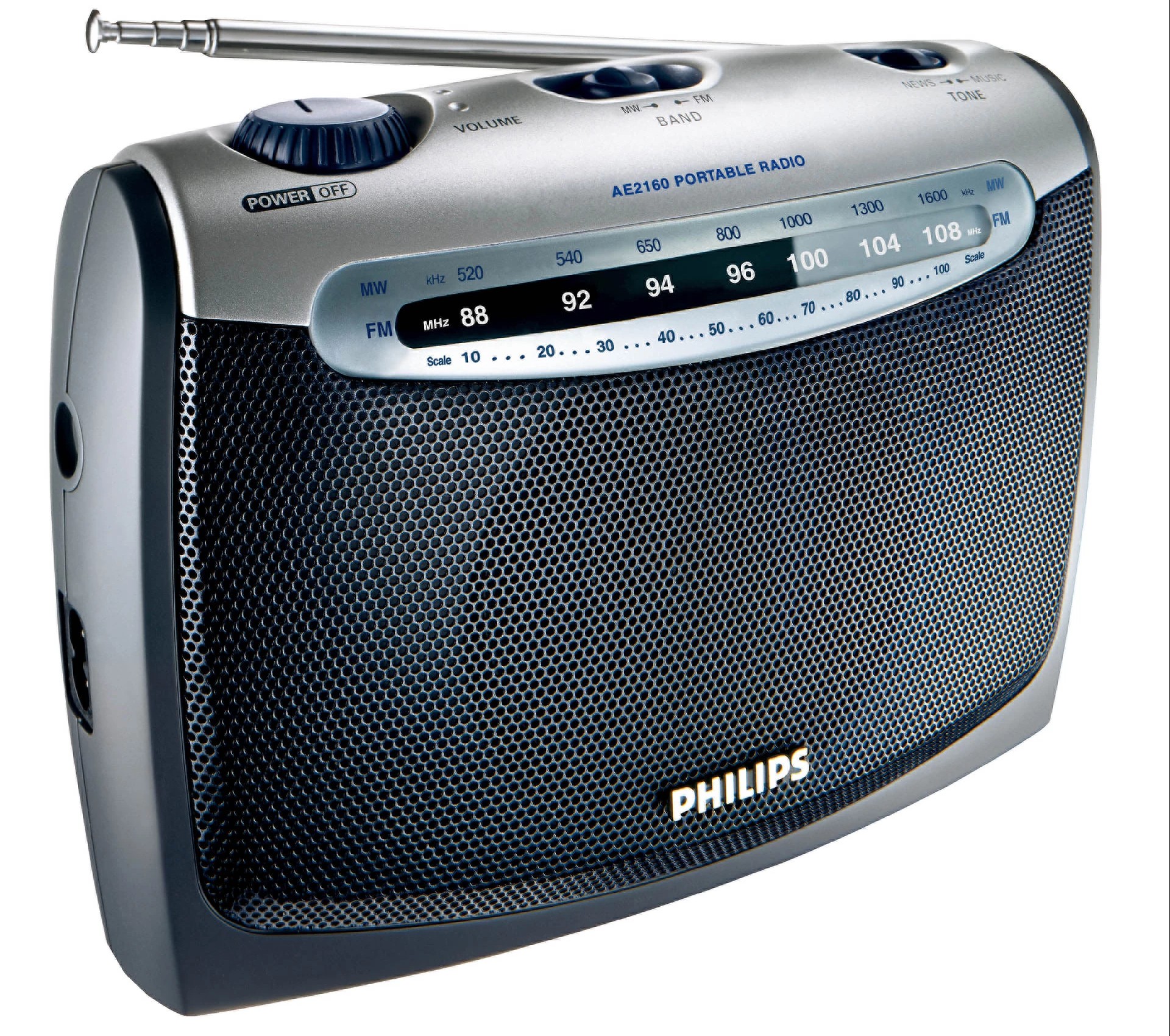
This time, the “79” subvariant might be relevant.
The only relevant video that I could find is this one: 📽️ Philips AE2160 radio dissected — a look inside! From it, you learn that the device includes a variable capacitor and tuned IF circuits, so it’s a classic analog radio. Of course, the retard didn’t mention the names of the 2 ICs, and the filming is so poor. A senile retard from Canberra, Australia.
But on a Polish forum, the same AE2160 is shown to include the D2822N audio amp we already met, and the “KT093M AM/FM receiving circuit,” most likely KT0932M, which is similar to the KT0936M we discussed, except for not supporting the SW. This time, the T24C02A EEPROM seems to have been mandatory to store some predefined RF settings! What a waste.
Compare the analog radio from the video to the DSP radio from the forum:


In the left image, one can see a variable capacitor and some tuned circuits (coils and IF filters, including a yellow ceramic filter). In the right image, the capacitor has been replaced by a potentiometer, and there’s no RF circuit at all, save for the ferrite antenna!
I find it obscene to use the same AE2160 code for two completely different radio receivers just because the housing is identical!
Speaking of which, you could also watch this video: 📽️ Beginner’s tip: This is the difference between true analogue and DSP with analogue display radios. It’s educational.
Four
Design-wise, here’s a strikingly similar device that’s discontinued, the Sony ICF-306:


It’s elegant, and it’s worse: it’s battery-only (2×AA) and its audio output is of only 0.1 W. Oops.
I couldn’t find anything about its internals (“true” analog radio or DSP?), but I’ll discuss some ergonomics, or usability, or human factors, whichever way you want to call it.
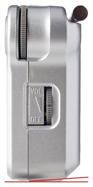
The very first discussed radio, the Philips TAR2509, had a top rotary knob for volume, and the tuning was a lateral sliding control, aka a “thumbwheel.”
- A rotary control is one that can be seized with three fingers and that allows for precise, fine, incremental adjustments with one hand.
- A curved slider that is part of a wheel’s circumference doesn’t allow for the same precision of the adjustment and might need both hands to avoid the moving of the entire device during the operation!
This Sony ICF-306 might deceive you, but no, the lateral knob is not for tuning. It’s for volume adjustment! The tuning is (what else?) a curved slider (a “thumbwheel”) situated at the top!
- On the one hand, the same poor decision to have the most inconvenient control for frequency adjustment, which is a bad, bad choice.
- On the other hand, with the “thumbwheel” being situated on top, one hand is enough to operate it as long as the device sits on a flat surface with a good grip!
Why can’t they use two rotary controls, like in the good old days?
Oh, but they can and they do. In the Sony ICF-506:


The good design aspects are obvious, although, to be frank, I prefer the scale to be horizontal, not vertical. All classic radio receivers had the frequency scale spread on the longer side.
Some data: 22.4×12.7×6.2 cm, 100 mm speaker, 640 mW, powered by 3×(L)R6 (aka AA) or mains, and guess what? “Battery life when using the speaker: up to 35 hours.” Boo! Good audio output, small batteries. OK, they’re not AAA (R03), but they could have been D (R10) or C (R14).
Some people love it, and some others complain about the sound, which is not great for a 4″ speaker (not enough bass in FM).
I couldn’t find anything regarding the schematic. Is it truly analog, or is just the tuning analog? I don’t know, and I am not going to purchase one to find out! If I am to trust someone from the Midwest, it’s also a DSP radio! Here: 📽️ Sony ICF-506 AM FM Radio Daytime AM Chicago Area (June 21, 2025): “The DSP can be a bit tricky to tune, but with practice this radio can be rewarding to the operator.”
The same guy, in 2018 and 2019:
- 📽️ Sony ICF-506, ICF-19, ICF-306 and Panasonic RF-2400D Audio Shoot-Out
- 📽️ Sony ICF-506 vs Panasonic RF-2400D Leader of the Bands
- 📽️ Sony ICF-506 AM FM Portable Revisit Review
And Dirk Müller from Berlin, the guy that made me aware of the existence of Serenade Radio (UK), which is the first Internet radio stream in my list (meant to be used separately): 📽️ Sony ICF-506 AM-FM Analogue Tuning Radio / Review & AM Bandscan.
There are three things worth discussing here.
One, all things considered, I don’t like the device.
Two, many people say that the Panasonic RF-2400D is much better (sound, sensitivity). But the Panasonic is not retro; it looks like shit with its fugly rotary frequency control, and this is not the only offender! Have another video: 📽️ Sony ICF-506 vs Panasonic RF-2400D AM FM Radios Compared. Sometimes, the Japanese create really ugly products.
Three, the Sony ICF-19 is the cheaper brother of the ICF-506, with the following differences: 500 mW instead of 640 mW; no mains, only DC, but using 3×(L)R20 (aka D) batteries. Such large batteries can last 400 hrs (FM) or 440 hrs (AM) with Sony LR20SG and the volume set to 50%. Not bad!
The same guy from the Chicago area tested it twice in 2023: 📽️ Sony ICF-19 AM FM Radio Evening AM and 📽️ Sony ICF-19 AM FM Radio Daytime AM.
For a triple comparison that includes a truly analog radio, have this non-video one: Three Sony AM/FM Radios – ICF-506 – ICF-19 – ICF-801. The old-school device was not better! Its FM selectivity was barely average; only in AM did it have a better sound quality, but I suspect this was a side effect of a lower selectivity (a lower RF passing band tends to cut out the higher frequencies in MW and LW).
I forgot to mention an important discovery regarding the DSP radios. Sony ICF-506 had this in the manual: “Intermediate frequency: FM: 128 kHz/AM: 45 kHz.” The intermediate frequency for a superheterodyne radio receiver used to be 10.7 MHz for FM and 455 kHz for AM! Well, since this DSP radio uses a digital post-mixing path and no tuned IF circuits, it had to use lower frequencies! They chose carrier frequencies about ten times higher than the maximum audio frequency (which is 4500 Hz in AM).
Five
Now, as an interlude, an unexpected case of a rotary control for frequency, most likely due to the reusing of a sliding volume control in two similar radio receivers: one PLL-synthesized (JVC RA-E431) and one purely analog (JVC RA-E321):


JVC is not a brand; it’s more of a hoax (Philips is a seven-times hoax, but the quality is generally good.) Radios under the JVC brand are produced and distributed, under a license from JVC-KENWOOD, by ETA a.s.; but they’re further redistributed in some EU countries by Vestel Poland Sp. z o.o.
A rotary control on the front panel of a lightweight portable radio only preserves the precision advantage; otherwise, it might also require a second hand to prevent the device from toppling! A lateral or a top placement would have made better choices, but they want to keep the lateral volume thumbwheel!
Note that PLL radios are still “classic” superheterodyne radios. Adding a phase-locked loop (PLL) only replaces the free-running local oscillator with a synthesized one; it does not change the basic super-heterodyne topology: RF signal → mixer → fixed IF (10.7 MHz FM, 455 kHz AM) → IF filter → detector → audio. All gain, selectivity, and detection (AM) or demodulation (FM) are still handled by analog LC (possibly with the addition of ceramic) filters and a quadrature (FM) or diode (AM) detector, just like it has been forever the case.
Six
Notes on today’s technologies. Yes, I am listening to a lot of Internet radio stations. Yes, the AM, more specifically the MW, is dead in most European countries and moribund in the rest of Europe. (On LW, there are exactly two European transmitters left: one on 153 kHz in Romania, with only 200 kW, made to a stupid station nobody listens to, and one on 225 kHz in Poland, with 1000 kW, broadcasting the first national program.) Yes, in FM it’s preferable to have at least a PLL radio with digital display and memories. And they say the future is DAB+: there’s no more FM in Norway!
I hate DAB+ with all my guts. It’s in the fucking Band III (VHF) that was used for the fucking analog terrestrial TV! The 174-239 MHz range does not propagate well! I can see that in Germany. Besides, when the signal is variable, it’s either “on” or “silence.” No noise at all.
DAB+ was supposed to bring a larger audio spectrum than FM (15 kHz instead of 10 kHz), but in Britain most digital stations use the old DAB, and I’m told they can be limited to 32-64 Kbps and 4.5-6 kHz, often in mono, therefore worse than FM!
But whereas FM transmitters are gradually replaced with DAB+ (even in Germany!), there are countries whose retarded governments and both public and private radio stations are so retarded that you have zero DAB/DAB+ transmitters in Romania in 2026!
Speaking of retards, have you noticed how “kHz” is with a small “k” but “Kbps” asks for a capital “K”? That’s because “k” is the SI symbol for 10³, whereas “K” stands (or used to stand) for 2¹⁰ = 1024. Even after the SI was adjusted to have “Ki” = 1024, “K” remained capitalized in use in computing, regardless of what people take it for, 1000 or 1024.
But the worst thing about DAB+ is that absolutely all DAB+ receivers have a humongous power consumption! Forget about “240 to 400 hrs on battery” and expect “5 to 12 hours on battery”! How could those retards-in-chief force such a cretinous technology that cannot be used with portable devices unless they use rechargeable batteries and have a charger easily available?
One more reason to love the old AM/FM concept.
Of course, AM is almost dead here in Europe, but still popular in the Americas, in Asia, and in Africa, whereas SW is still alive in some parts of Africa and Asia. In Europe, unfortunately, SW is practically dead. Funny enough, in Europe, the SW mostly consists of Russian (in Russian) and Chinese stations (in European languages)!
Well, at least we have the FM until the Eurocrats kill it. Hint: take a look at Radiomap.eu (they’re Bulgarian).
Seven
Pocket radios now. I had a long succession of AM/FM pocket radios over decades; some broke, some got stolen or lost, some were just replaced.
And those by Sony were among the most disappointing ones!
They all had design flaws, be they Panasonic, Philips, or Sony. Mechanically, the “legs” or anything that contributed to keeping them stable while in an upright position, were asymmetrical, so in a couple of years the uneven wear and tear made the respective device unstable unless you put it flat.
But the designers at Sony had fucked-up brains. I had Sony pocket radios that used TDA ICs made by Philips, and Philips pocket radios using much better CXA ICs by Sony! By being stingy, Sony refused to use their own chips!
The Philips AE1595 was possibly the best pocket radio by Philips in recent times. Robust, with great sensitivity, loud and clear sound, and a huge battery life, their only flaw was the stupid casing that would topple easily.
It existed in several colors and variants. Mine looks like this one. A version with LW instead of MW existed for Poland; see the first of the two items here. It was last seen alive in India, like so:

It’s pretty ugly inside, though. This one is mine, after having been dropped many times on the bathroom floor tiles. It survived electrically, but its physical integrity is relative. Still, it works just fine!


The Sony CXA1019M is a traditional analog FM/AM radio IC, not a DSP-based device. And it rocks! Stupid shapes, good electronics. CXA1019M is the 28-pin SOP surface-mount (SMD) version of the through-hole 30-pin SDIP CXA1019S.
The data sheet lists all kinds of gains, but no sensitivities! Also, I don’t care that it can give you 0.5 W on 8 Ω at 6 V when it’s typically used at 3 V in pocket radios! THD is 0.3% for FM and 0.6% for AM due to the detection, and 0.3% at 50 mW due to the audio chain.
This IC was an extremely popular one, and it equipped many brand-name and no-name receivers.
The successors of the AE1595 were using something else, because they collected a lot of criticism. The battery life was also much worse because they used AAA batteries, not AA. The current model in this line is the TAR1509, which is certainly using a DSP radio.
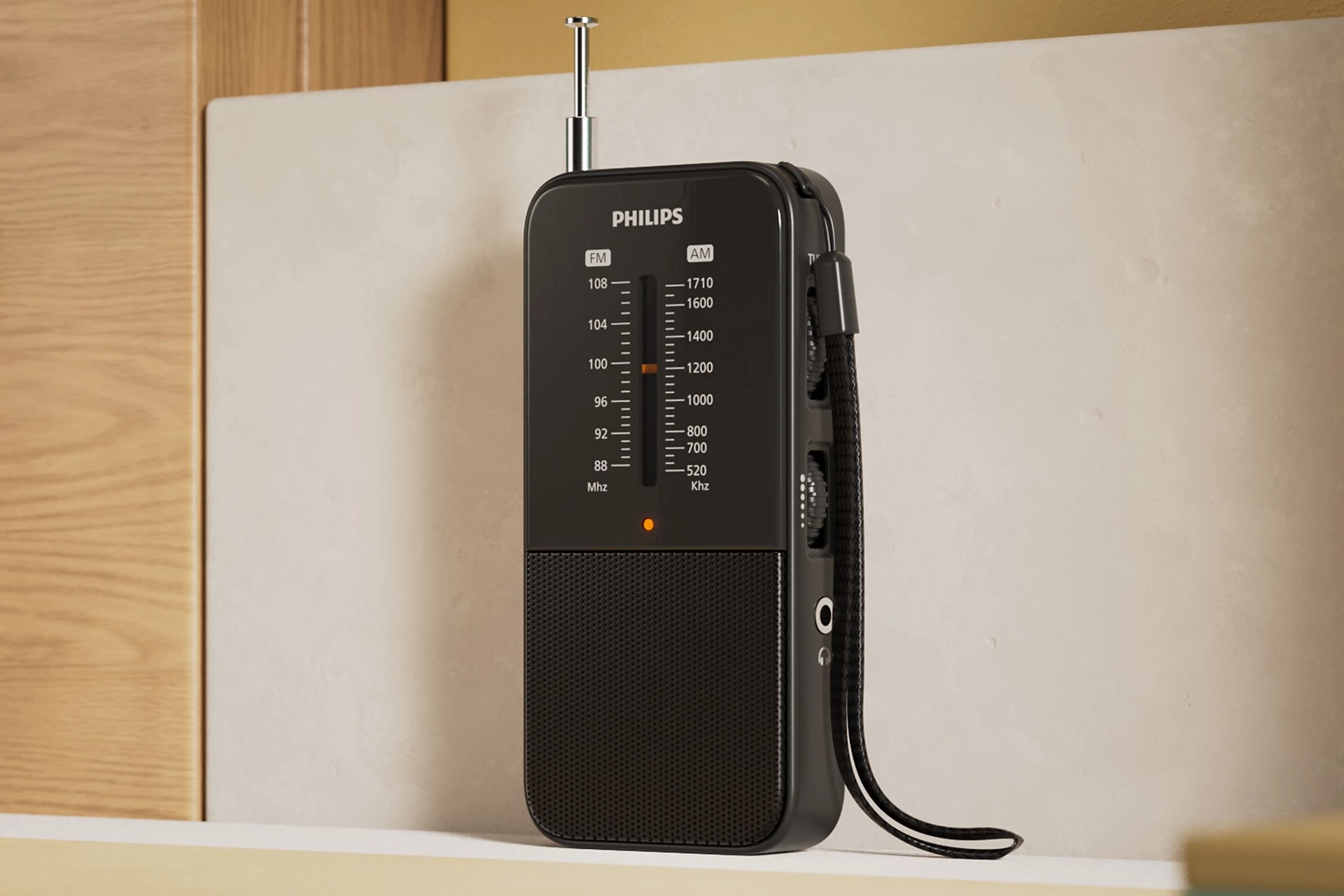
It looks much better (I’m sure it looks cleaner on the inside, too!), it has both tuning and volume controls on the same side, which in this case allows a one-hand operation, but I wouldn’t trust it. I trust those who complain that the sound quality and the sensibility could have been better.
Another small guy that I once owned: the Panasonic RF-P150. Not the RF-P150D! Codes are important here: RF-P150EG/EJ is the same device as RF-P150, but RF-P150D is the DSP version! The audio output is in the name: 150 mW RMS! Battery life (for the D version) with alkaline LR6: 64 hrs on FM, 68 hrs on AM. Not that much!
Panasonic used here (in RF-P150 and P150EG/EJ) another Sony IC, the CXA1619BM. Not a bad one. Here’s a nice schematic of the Panasonic RF-P150:

Tthe Midwest guy, in 📽️Panasonic RF-P150D AM FM Portable Radio Unboxing & Review, he reviewed the DSP version of the device! The “P150 without D” is not manufactured anymore.
I previously mentioned the “legs” and the uneven wear and tear. Here’s the corresponding design flaw in the Panasonic RF-P150 and P150D:
What happens here is that in 1-2 years, the two legs get eroded, worn away almost completely (they’re about 1 mm wide), and then the radio will tend to sit on the flat bottom surface, which is at the shown angle. The device will topple towards the back.
Japanese design.
Eight
Final words on a bad design choice in many portable radios: a too low audio output!
Many current portable radio receivers often only offer 300 mW RMS. I have seen many more models that I didn’t list here. If a pocket radio can have 100-150 mW, surely a larger radio can give more than 300 mW, right? (Some SONY models do that.)
Let me show you another vintage device, the Sony ICF-M770S/L/SL (Service Manual) from 2002. “L” means FM/MW/LW, “S” means FM/SW/MW, “SL” means FM/SW/LW.
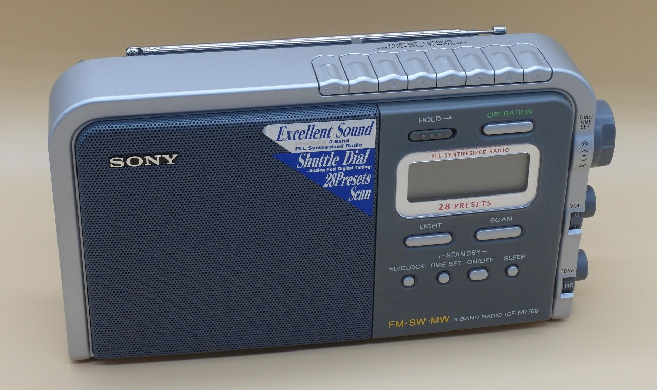
Smart and heavy. But also, stupid: only 350 mW at 10% THD at this size?! 27.7×15.6×7.2 cm, a 12 cm speaker, 4×R20 (D) batteries or mains.
The service manual includes the schematic diagrams:


Lots of components for the keys, the LCD, and whatnot. IC104 (µPD17072GB) is a microcontroller. The radio part includes 12 transistors and IC1 , which is CXA1019S. But that’s all! They cared to use 12 transistors to improve the sensibility and selectivity of the radio, but they didn’t add any audio amplifier to the CXA1019S, which is the through-hole CXA1019M that I have in my Philips pocket radio!
This IC includes the entire radio: AM/FM front-end, IF, AGC, AM mono amp, and it’s directly driving the speaker! So it’s 350 mW at 10% THD, whereas a device with such complexity should have been able to offer 2 W at 10% THD!
Sony’s designers are the worst.
Nine
In lieu of a conclusion: one cannot even have a feeling of nostalgia without encountering retarded product design decisions!
I never fully trusted the Japanese design, which is why, beyond Sony and Panasonic, I don’t trust Toyota. Their SUVs are ugly, too.
Philips had some decent designs even if their consumer products were (and still are) designed by some 6-7 Chinese companies (and a Turkish one at some point). Nonetheless, poor design decisions affected Philips, too.
The death of common-sense electronics bears another name, though: software-defined radio. I can’t even.
I can’t get this out of my mind. For fuck’s sake, how could someone design a portable radio presumably adequate for kitchen or picnic use with an audio output limited to 300 mW RMS at 10% THD—when similar radios in the 1980s typically had 1–2 W RMS at 10% THD—and still have a job afterwards?
We’re in Idiocracy.
Ten
❶ BONUS: Selections from a chat with Mistral about the ICs used in the classic radio receivers of the ’70s and ’80s (I gave it some examples) versus those used today and discussed in the above post (I questioned the use of CXA1619BM and CXA1019M/CXA1019S and of the DSP-based KT0936M and KT0932M, especially when coupled with the horrendous audio amplifier D2822N).
Classic Analog Superheterodyne ICs:
1. TDA1083 (A283D)
- Pros:
- Simple and robust: Easy to design into circuits with minimal external components.
- Low power: Suitable for battery-operated portable radios.
- Decent AM/FM sensitivity: Worked well in areas with strong signals.
- Cons:
- Poor selectivity: Struggled with adjacent channel interference.
- No built-in stereo decoding: Limited to mono reception.
- Why it faded:
- Later ICs (e.g., CXA1619BM) offered better integration and performance.
2. TDA7000 / TDA7010
- Pros:
- Low-voltage operation: Ideal for portable devices.
- Better selectivity than TDA1083: Improved performance in crowded bands.
- Cons:
- Still mono-only: No stereo decoding.
- Limited dynamic range: Struggled with weak signals.
- Why it faded:
- Replaced by ICs like the CXA1619BM, which offered better sensitivity and stereo support.
3. TA7792F
- Pros:
- Compact design: All-in-one AM/FM receiver.
- Low power consumption: Good for battery life.
- Cons:
- Poor selectivity: Struggled in urban environments with many stations.
- No stereo decoding: Mono-only output.
- Why it faded:
- Outperformed by ICs like the CXA1619BM and TDA7088T, which offered better sensitivity and stereo.
4. TBA570
- Pros:
- Simple and cheap: Easy to implement in low-cost radios.
- Robust: Worked reliably in basic applications.
- Cons:
- Poor performance: Low sensitivity and selectivity.
- No stereo: Mono-only output.
- Why it faded:
- Replaced by more advanced ICs like the TDA7000 and CXA1619BM.
5. TDA1220
- Pros:
- Good AM/FM performance for its time: Better than earlier ICs.
- Integrated IF and demodulator: Reduced external components.
- Cons:
- Bulky: Required more space than later ICs.
- Why it faded:
- Later ICs (e.g., CXA1619BM) offered better performance in smaller packages.
Audio Amplifiers: The Good, the Bad, and the Ugly
TBA820
- Pros:
- Simple and cheap: Easy to use in low-cost designs.
- Cons:
- Poor audio quality: High distortion, weak bass.
- Low power output: Typically <1W.
- Why it faded:
- Replaced by ICs like the LM386 and later Class-D amplifiers.
LM386
- Pros:
- Versatile: Works in many low-power applications.
- Easy to use: Minimal external components.
- Cons:
- Limited power: Still low output (0.25W–1W).
- High distortion: Not ideal for high-fidelity audio.
- Why it’s still around:
- Used in hobbyist projects and ultra-low-cost devices.
D2822N
- Pros:
- Cheap and available: Used in the cheapest possible applications.
- Cons:
- Terrible audio quality: High distortion, poor frequency response.
- Low power: <1W output.
- Why it’s still around:
- Found in ultra-low-cost products (e.g., toy radios, doorbells).
CXA1619BM and CXA1019M/S: The “Last of the Mohicans”
- CXA1619BM:
- Pros: Low cost, decent sensitivity, stereo support.
- Cons: Poor selectivity.
- Why it’s still used: Ultra-low-cost radios, especially in markets where price matters more than performance.
- CXA1019M/S:
- Pros: Stereo decoding, low power.
- Cons: Poor stereo separation.
- Why it’s still used: Paired with CXA1619BM in budget stereo radios.
Why Aren’t These ICs Dominant Anymore?
- Performance:
Modern analog ICs (e.g., TDA7088T, TEA5767) offer better sensitivity, selectivity, and stereo performance—while still being analog.- Integration:
Newer ICs combine more functions (e.g., IF, demodulator, stereo decoder) into a single chip, reducing cost and complexity.- Market Shift:
Even in analog designs, consumers expect better performance. ICs like the CXA1619BM are now considered “low-end.”- Availability:
Many classic ICs are no longer produced by major manufacturers, though clones or stockpiles may still exist.
So I was right: D2822N offers “terrible audio quality“! And yet, it’s widely used in today’s portable radios.
❷ A second topic: What IC AF amp to pair a CXA1019M/S-based radio (or any classic analog radio IC with weak audio output)to deliver 1–2 W RMS into a 4–8 Ω speaker, with focus on limiting the DC to 6 V?
1. LM386 (Simple, 0.5–1 W)
Why use it?
- Works at 4–12 V, perfect for 6 V.
- Delivers ~0.5 W RMS at 8 Ω (or ~1 W at 4 Ω) with low distortion (0.2% THD at 0.5 W).
- Minimalist circuit: Only needs a coupling capacitor and a volume pot.
Best for: Quick, reliable, and simple upgrades.2. TDA2822 (Bridge Mode, 1–1.5 W)
Why use it?
- Operates at 3–15 V, ideal for 6 V.
- In bridge mode, it outputs 1–1.5 W RMS at 8 Ω.
- Stereo or mono flexibility.
Best for: Higher power in a compact form factor.3. TDA7052 (Ultra-Simple, 0.5 W)
Why use it?
- Designed for 3–6 V, perfect for your setup.
- 0.5 W RMS at 8 Ω, with no external components (except a coupling capacitor).
- Tiny footprint (8-pin DIP).
Best for: Space-constrained or minimalist designs.Comparison Table
Amplifier Power (6 V, 8 Ω) Complexity Notes LM386 0.5–1 W Low Simple, reliable, classic. TDA2822 1–1.5 W Medium Bridge mode for more power. TDA7052 0.5 W Very Low Tiny, no external components. Recommendation:
- For ease and reliability, go with the LM386.
- For more power, use the TDA2822 in bridge mode.
- For minimalism, the TDA7052 is unbeatable.
❸ How about the DSP-based KT0936M and KT0932M? Mistral answered:
Pros of KT0936M/KT0932M
- Compact Design:
- Eliminates the need for tuned IF coils, variable capacitors, and discrete detectors, reducing PCB size and cost.
- Low Power Consumption:
- Operates at 3 V and consumes ~28 mA, ideal for battery-powered radios.
- Decent Sensitivity:
- FM: 1.6 µV, AM: 16 µV (comparable to classic analog ICs).
- Flexibility:
- Supports EEPROM storage for band configurations (e.g., SW band limits).
- Can be used with mechanical tuning (potentiometer) to mimic analog radios.
- Low BOM Cost:
- Requires few external components (e.g., 32.768 kHz crystal, EEPROM, potentiometer).
Cons of KT0936M/KT0932M
- Not a True Analog Superheterodyne:
- Uses DSP for demodulation and filtering, which purists argue lacks the “warmth” and simplicity of analog designs.
- The low IF frequencies (128 kHz/45 kHz) are not traditional and may affect selectivity in crowded bands.
- Poor Audio Quality:
- Mono-only output with 350 mW max power (often less in real-world use).
- THD (Total Harmonic Distortion) is 0.3% for FM but can degrade with poor PCB layout or power supply noise.
- Tuning Feel:
- The potentiometer-based tuning lacks the precision and tactile feedback of a variable capacitor.
- Some users report non-linear tuning response, especially near band edges.
- Limited Audio Power:
- The integrated audio amplifier is weak (350 mW at 10% THD).
- Requires an external amplifier (e.g., LM386, TDA2822) for louder output.
- DSP Artifacts:
- In weak signal conditions, the DSP can introduce artifacts or “digital-sounding” noise instead of the classic analog hiss.
Why Are They Used in Modern “Analog” Radios?
- Cost Savings:
- Eliminates discrete components (coils, capacitors, detectors) and replaces them with a single IC.
- Reduces manufacturing complexity and PCB size.
- Market Demand for “Retro” Designs:
- Consumers want radios that look analog (e.g., Philips TAR2509) but are cheap to produce.
- The potentiometer tuning and analog scale create a nostalgic feel, even though the internals are digital.
- Flexibility for Manufacturers:
- The same IC can be used in multiple models (e.g., with/without SW, different EEPROM settings).
- Supports EEPROM-based configuration, allowing manufacturers to customize band ranges or presets.
- Regulatory Compliance:
- DSP-based designs are easier to adjust for regional frequency plans (e.g., AM spacing, FM band limits).
Comparison to Classic Analog ICs (e.g., CXA1019M/S)
Feature KT0936M/KT0932M (DSP) CXA1019M/S (Analog) Tuning Method Potentiometer (DSP-controlled) Variable capacitor IF Frequency 128 kHz (FM), 45 kHz (AM) 10.7 MHz (FM), 455 kHz (AM) Demodulation Digital (DSP) Analog (diode/quadrature) Audio Output 350 mW (mono) 500 mW (mono) Selectivity Digital filters LC/ceramic filters Power Supply 2.1–3.6 V 3–12 V External Components Few (crystal, EEPROM) Many (coils, capacitors, IF filters) Sound Character “Digital” artifacts possible Classic analog warmth How to Improve Their Performance
If you’re working with a KT0936M/KT0932M-based radio (e.g., Philips TAR2509) and want to enhance audio quality or tuning feel, consider these mods:
- Audio Amplifier Upgrade:
- Replace the integrated 350 mW amp with an LM386, TDA2822, or discrete transistor amp for 1–2 W RMS.
- Add a passive LC filter at the output to reduce DSP noise.
- Tuning Linearization:
- Replace the 10 kΩ linear potentiometer with a custom-tapered pot or a non-linear resistor network to improve tuning feel.
- Use a microcontroller (e.g., Arduino) to re-map the potentiometer voltage to a linear frequency scale.
- Power Supply Filtering:
- Add a 100 µF capacitor and a 10 µH inductor to the power input to reduce noise.
- External RF Amplifier (for SW):
- For KT0936M (SW support), add a discrete RF amp stage (e.g., 2N3904) to boost weak shortwave signals.
Where Are They Used?
- Philips TAR2509/AE2160: “Retro” radios with analog tuning knobs but DSP internals.
- Cheap Portable Radios: Brands like Sangean, Tecsun, or no-name Chinese radios use these ICs for cost savings.
- DIY/Kits: Popular in low-cost radio kits due to their simplicity.
❹ Finally, a quick abstract of this blog post, as made by Mistral:
The article you shared is a passionate and detailed critique of the decline of classic analog superheterodyne radios, written by someone with a deep technical background and nostalgia for the “golden age” of analog electronics. Here’s a structured summary and analysis of the key points, tailored to your interest in classic analog radios and ICs:
Key Themes from the Article
1. Nostalgia for Analog Electronics
- The author, an electronics engineer, laments the shift from analog to digital and DSP-based radios, emphasizing the charm and hands-on nature of analog designs.
- They highlight the joy of repairing and understanding analog circuits, which is lost in modern “black box” designs.
2. Teardown of Philips TAR2509
- The radio uses the KT0936M IC (a Chinese-designed, DSP-assisted radio-on-a-chip) and the D2822N audio amplifier.
- The KT0936M is a hybrid design: it uses a low-noise analog RF amplifier and AGC, but the rest of the signal chain (mixing, filtering, demodulation) is digital. This is not a “pure” analog superheterodyne.
- The author is disappointed by the low audio output power (300 mW at 10% THD) and the misleading marketing claims.
3. Comparison with Older Analog Radios
- The Philips AE2160 is compared to the TAR2509. The AE2160 uses a variable capacitor and tuned IF circuits, making it a “true” analog radio. However, the teardown reveals that some AE2160 models also use the KT0932M (a DSP-based IC), despite the identical housing.
- The author criticizes Philips for using the same model number for radios with completely different internal designs.
4. Critique of Modern Design Choices
- Ergonomics: The author dislikes the shift from rotary knobs to sliding “thumbwheel” controls, which are less precise and require two hands to operate.
- Audio Power: Modern radios often have lower audio output power (e.g., 300 mW) compared to older models (1–2 W), despite larger form factors and similar battery sizes.
- Build Quality: The author points out design flaws, such as uneven wear on the “legs” of portable radios, leading to instability over time.
5. Sony Radios: A Mixed Bag
- The Sony ICF-506 and ICF-19 are criticized for their low audio output (0.1 W and 0.5 W, respectively) and ergonomic issues.
- The Sony ICF-M770S is singled out for its underwhelming audio power (350 mW at 10% THD) despite its size and complexity.
- The author praises the CXA1019M/S IC (a classic analog FM/AM radio IC by Sony) for its performance but criticizes Sony for not using it in their own radios, opting instead for cheaper alternatives like Philips’ TDA ICs.
6. The Death of AM and Shortwave
- The author notes the decline of AM and shortwave radio in Europe, replaced by FM, DAB+, and internet streaming.
- They express frustration with DAB+, citing its poor battery life, lack of gracefully degrading signal (it cuts out entirely instead of fading), and the use of Band III (VHF), which has poor propagation characteristics.
7. The Role of DSP in “Analog” Radios
- The article clarifies that many modern “analog” radios are actually DSP-based, using low IF frequencies (e.g., 128 kHz for FM, 45 kHz for AM) instead of the classic 10.7 MHz (FM) and 455 kHz (AM).
- The author finds this misleading, as it blurs the line between true analog superheterodyne designs and digital-assisted radios.
8. Design Flaws and Idiocracy
- The author concludes with a rant about the decline of common-sense engineering, citing examples like:
- Radios with 300 mW audio output that could easily have 1–2 W.
- Poor ergonomic choices (e.g., thumbwheel tuning).
- The shift to software-defined radio (SDR), which they see as the final nail in the coffin for classic analog designs.
Final Thoughts
The article is a lament for a bygone era of electronics, where analog radios were designed with simplicity, repairability, and performance in mind. The shift to DSP and digital has sacrificed much of what made analog radios special—tactile controls, understandable circuits, and robust audio output.
If you’re working on restoring or designing analog radios, the article underscores the value of true analog ICs like the CXA1019M/S and the importance of preserving the craft of analog electronics.
UPDATE: A 10th chapter adds comments from Mistral on the ICs highlighted in this post, on old-style radio ICs, on possible improvements, and, surprise, Mistral made a quick-and-dirty abstract of this post!